Multiplexing a dual seven segment display
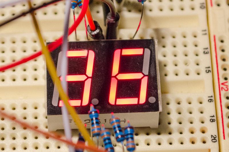
Following on from driving a seven segment with an ATTiny2313a last post I swapped out the single seven segment for a dual seven segment that I bought from AliExpress. This one was a dual display with a similar set of 10-pin inputs like the last, single one. The pins from A-G+DP are different to the last, but more tellingly instead of two anode pins for the single display, there is now an anode pin for each segment. Power one pin with some of the LEDs pulling to ground and one lights up, power the other and the other one lights up. And if you power both, you get both sides displaying the same thing.
I found a post at (codeandlife.com) that helped me out with the timers & interrupts, which again I’ve found harder to find relevant code for:
Here we need to multiplex. What is that? Well, multiplexing is described as:
Telecommunications. of, relating to, or using equipment permitting the simultaneous transmission of two or more trains of signals or messages over a single channel.
In this case, to drive one seven segment we have already used 7 pins + power. If we added another stand alone display, that would become 14. What about building a clock with 4 digits, do we go and get an MCU with 28 or more pins?
Nope. What we do is setup an array of seven segments (two in this proof-of-concept case) which share a common set of lines to drive each LED. But we split the input lines (in this case anode) to the LEDS so we can drive them independent of each other. This enables us to set the AVR pins to sink current to enable one number, and turn the first part of the display on. After a brief delay, we turn that segment off, change the AVR pins for the second number, and turn on the second part of the display.
I’ve measured this rig at between 5-15mA, depending on what is lit up (with a number 8 being the most)
Warning: Keep in mind as well that an ATTiny2313a is rated to 20mA sourcing of current. Exceed that and you might burn it out!
If we do this very fast (I measured the frequency at around 250mhz) the human eye blends together images and we see both sides lit up simultaneously. This is extremely common and you may be surprised to find where this occurs. If you have a DSLR, try taking very short exposures of LED displays!
Wiring up the breadboard
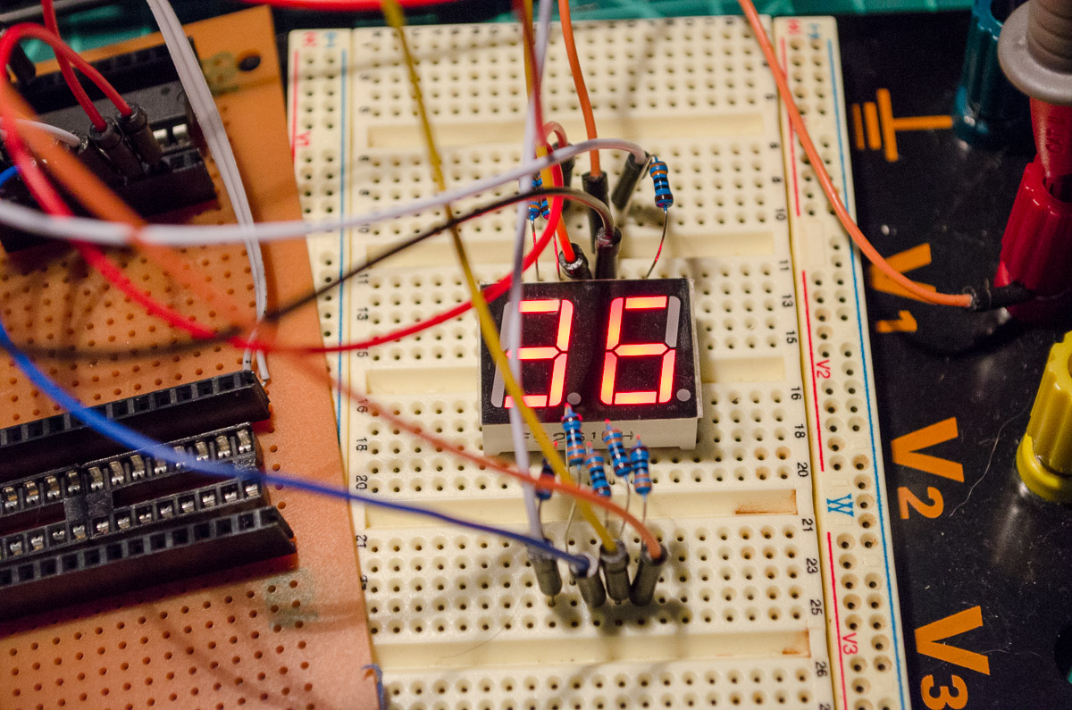
So I rewired the breadboard up similar to last time, but taking into account the different pins. Also, instead of +5 going to one of the anode pins of the seven segment I wired one anode of the seven segment to PD4 and the other to PD5 of the ATTiny2313 - this time the AVR will drive the anodes.
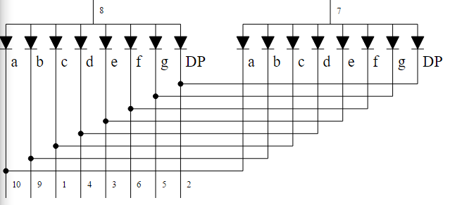
| avr-pin | letter | led-pin |
|---|---|---|
| PB7 | A | pin 10 |
| PB6 | B | pin 9 |
| PB5 | C | pin 1 |
| PB4 | D | pin 4 |
| PB3 | E | pin 3 |
| PB2 | F | pin 6 |
| PB1 | G | pin 5 |
| — | — | — |
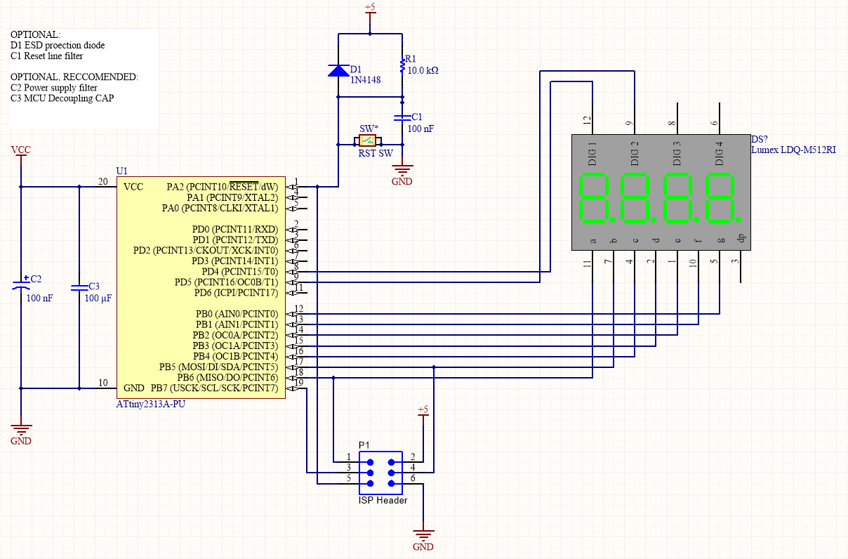
Schematic
Info: I couldn’t find a common-anode dual seven segment display on octopart - this is a quad display but imagine its only a dual display.
Warning: The pinouts on this dont match above, again because the part isn’t present. If you follow this, check your part datasheet.
Code
With the below code, the display counts from 0-99. Brightness is fine, but can be a problem with more displays. AVR is running interal clock with clockdiv/8 fuse set.
Here we use a timer to increment a counter each second. A second timer runs the multiplexing, with ~500 interrupts per second. Thats almost it!
Info: I have started using bit flipping defines for legible code and easy of use. Might annoy the purists!
/*
 * PoorMansSevenSegment.cpp
 *
 * A bodge program to run a seven segment without a BCD - 7 segment display decoder
 *
 * Created: 15/05/2016 6:50:30 PM
 * Author : Nat
 */

#define F_CPU 1000000UL //CPU speed, set clockdiv/8
#include <avr/io.h>
#include <util/delay.h>
#include <avr/interrupt.h>

// Defines for  easy bit flipping
#define    bit_set(...)        bit_set_(__VA_ARGS__)
#define    bit_set_(x,y)        x |= 1<<y            // set a bit
#define    bit_clear(...)        bit_clear_(__VA_ARGS__)
#define    bit_clear_(x,y)        x &= ~(1<<y)            // clear a bit
#define    bit_test(...)        bit_test_(__VA_ARGS__)
#define    bit_test_(x,y)        (!!(x & (1<<y)))        // test a bit

/*** following macros related to the PORTx - register only !    ***/
/***                                ***/
#define    bit_dir_outp(...)    bit_dir_outp_(__VA_ARGS__)
#define    bit_dir_outp_(x,y)    *(&x-1) |= 1<<y            // access DDRx of PORTx !
#define    bit_dir_inp(...)    bit_dir_inp_(__VA_ARGS__)
#define    bit_dir_inp_(x,y)    *(&x-1) &= ~(1<<y)        // access DDRx of PORTx !
#define    bit_test_in(...)    bit_test_in_(__VA_ARGS__)
#define    bit_test_in_(x,y)    (!!(*(&x-2) & (1<<y)))        // access PINx of PORTx !

// pin defines
#define PORT_LED PORTB
#define DDR_LED DDRB
#define PORT_PWR PORTD
#define DDR_PWR DDRD

// define Seven segment output ports for Vcc to Seven Segment
#define LED0    PORTD, 4
#define LED1    PORTD, 5

//binary representations of binary required to light seven segment 0-9
unsigned int pins[] = {0b11111100, 0b01100000, 0b11011010,0b11110010, 0b01100110, 0b10110110, 0b10111110, 0b11100000, 0b11111110, 0b11100110};
volatile int i_timer_seconds = 0;
volatile int i_active_display = 0;

void seven_write(int i_digit) {
    // write to entire LED port - invert due to the fact that in a common anode display LOW = on.
    // to use in a common cathode display, remove inversion.
    PORT_LED =~ pins[i_digit];
}

ISR(TIMER1_COMPA_vect) {
    // increment timer count
    i_timer_seconds++;
}

ISR(TIMER0_OVF_vect) {
    PORT_PWR &= ~(1 << (i_active_display+4));    // turn off LED
        //toggle active display
    i_active_display ^= 1;

    if(i_active_display == 0) {
        seven_write(i_timer_seconds % 10);
    } else {
		seven_write(i_timer_seconds / 10 % 10);
    }

    PORT_PWR |= (1 << (i_active_display+4));    // turn on LED
}

int main(void)
{
    //disable interupts
    cli();

    //Data Direction Register, set all bits high
    DDR_LED = 0xFF;                // enable entire LED port as output

    // set led common anode wires to outputs (PD4/5)
    bit_dir_outp(LED0);
    bit_dir_outp(LED1);

    // init timer 0
    TIMSK |= (1 << TOIE0);  // timer 0 overflow interupt
    TCCR1B |= (1 << WGM12);  // config for CTC mode
    TIMSK |= (1 << OCIE1A);  // CTC interupt
    OCR1A |= 15625;             // prescaler
    sei();
    TCCR0B |= (1 << CS01); //timer 0 at clk/8
    TCCR1B |= (1 << CS11)+(1 << CS10); //timer 1 at clk/64

    while (1) {}
    return 1;
}