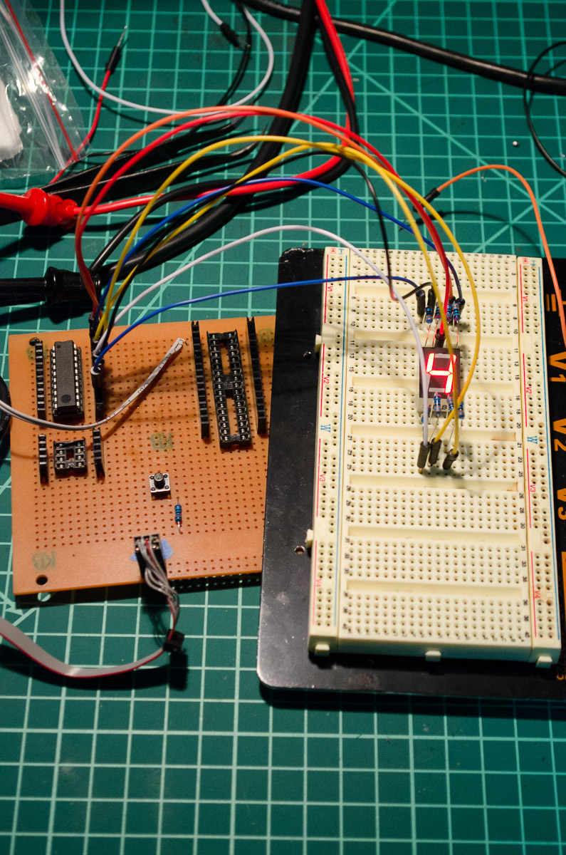
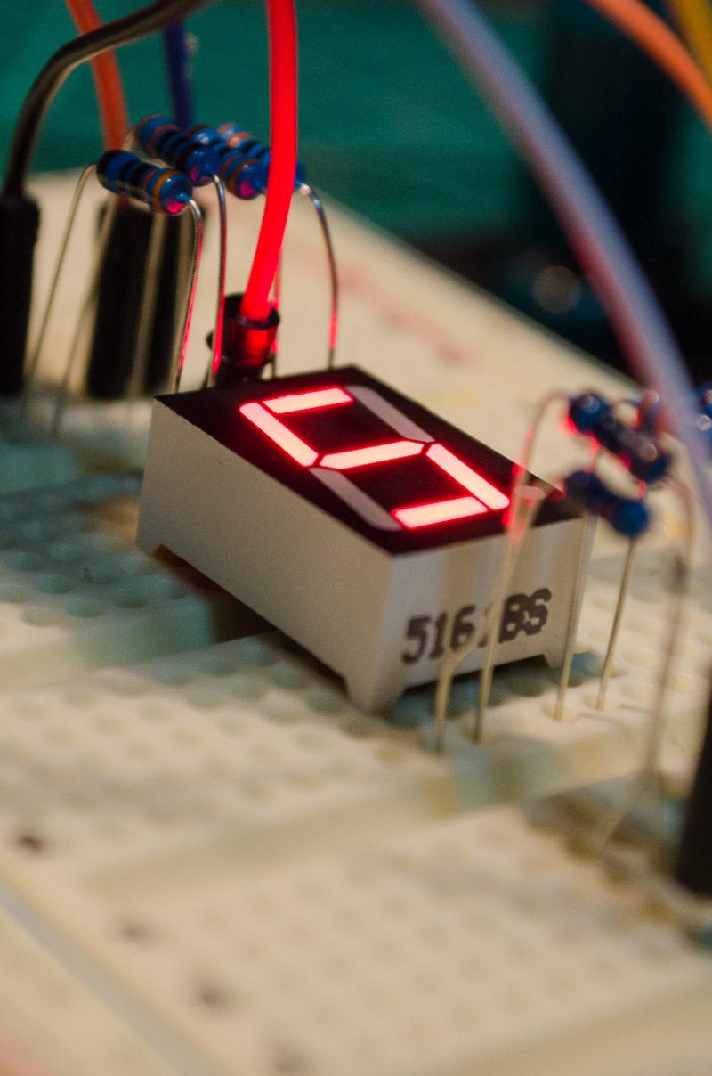
Driving a seven segment display with no BCD to seven segment chip
I have gotten a batch of cheap seven segments from DealExtreme, and it was high time I put them through their paces.
However, I have no BCD to seven segment chips. No matter, I can bodge it up just using 7 pins. So I ran through some code to just drive each segment with a pin from an ATTiny2313a.
I found from the data-sheet for the 7-seg LED that it was a common anode. So that means I had to drive LOW to sink current to light LEDs - and keep HIGH to keep segments off.
Starting off by working out the seven segment display and working out in a table which logic levels for each led; to drive the segments for numbers 0-9. I’m sure it was searchable online, but where’s the fun in that?
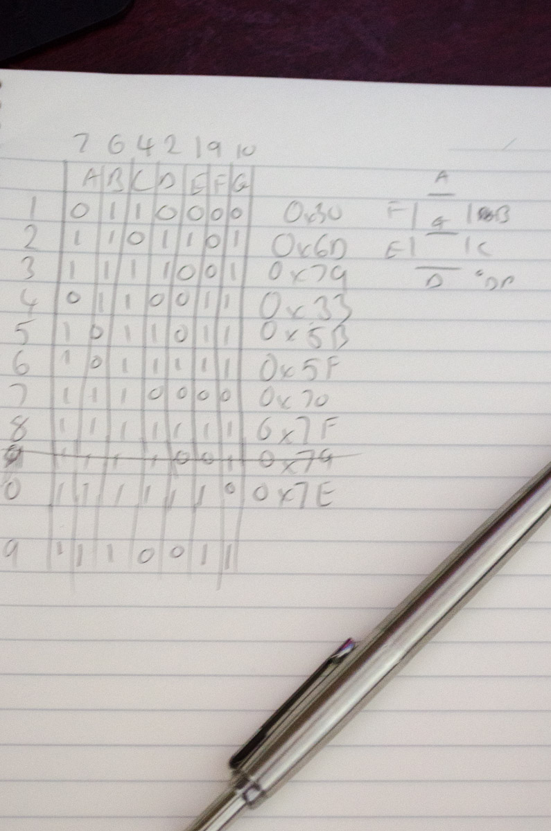
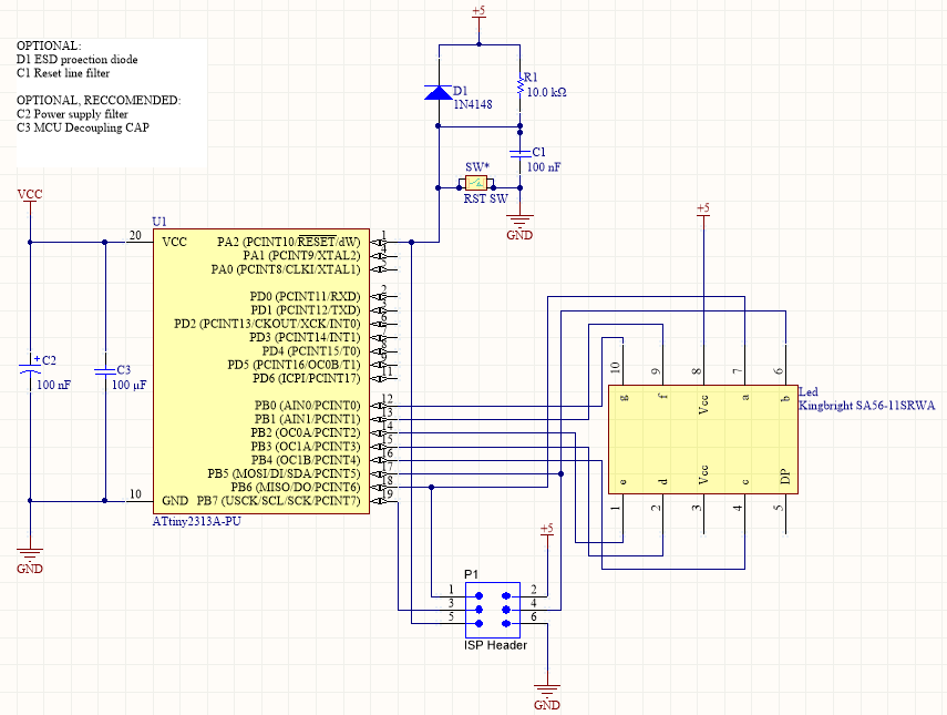
Using my new target board to hook up the 2313a to a breadboard - with 330Ω from each LED. I saw from the datasheet for the LED seven segment that it had common anode on pins 3 & 8. Using the pinout below I was able to breadboard connections. It was a simple case of matching up PB0-PB7 to match up with the led segments from the datasheet, via the letters.
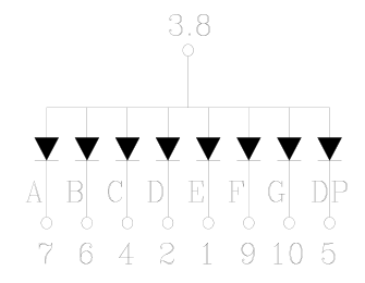
I hooked up PB0 through PB7 to the seven segment display, using the pinouts above to correlate to the pinouts I drew out. I did get tripped up on the direction here - thinking that PB0 was the highest bit in the register! Of course, it isn’t!
So I ended up with:
| avr-pin | letter | led-pin |
|---|---|---|
| PB7 | A | pin 7 |
| PB6 | B | pin 6 |
| PB5 | C | pin 4 |
| PB4 | D | pin 2 |
| PB3 | E | pin 1 |
| PB2 | F | pin 9 |
| PB1 | G | pin 10 |
| — | — | — |
Info: Pin 0 is not connected! When I added the binary to the code I added a trailing 0 to the binary to bump it up to 8-bit.
Schematic
Code
/*
 * PoorMansSevenSegment.cpp
 *
 * A bodge program to run a seven segment without a BCD - 7 segment display decoder
 *
 * Created: 15/05/2016 6:50:30 PM
 * Author : Nat
 */

#define F_CPU 8000000UL //CPU speed, remove clockdiv/8
#include <avr/io.h>
#include <util/delay.h>

int main(void)
{
    //binary representations of binary required to light seven segment 0-9
    int pins[] = {0b11111100, 0b01100000, 0b11011010,0b11110010, 0b01100110, 0b10110110, 0b10111110, 0b11100000, 0b11111110, 0b11100110};
    int count = 0;

    DDRB=255; //Data Direction Register, set all bits high

    while (1)
    {
        for(count=0; count<10; count++) {
            //change output of entire portb register to above hex (inverted, as its common anode and LED on requires sinking current.
            PORTB=~pins[count];
            _delay_ms(1000);
        }
    }
    return 1;
}
End result
